
I. Hydraulic Actuation Wet or Dry Operation
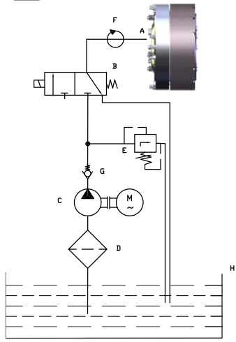
Schematic # 1: Displays a typical circuit diagram for a hydraulically actuated wet or dry-running disc clutch. The pump (C) draws the oil through the filter (D) from the reservoir (H) and passes it under pressure to the operating pipeline. The operating pressure is adjusted by the limiting valve (E). Any excess oil flows back to the reservoir. The clutch (A) is operated when the “ON” position of the control valve (B) is selected.
A. Clutch
B. 3/2 Control Valve
C. Fixed Displacement Pump
D. Filter
E. Pressure Limiting Valve
F. Rotary Connection
G. Non-Return Valve
H. Oil Reservoir
II. Pneumatic / Air Actuation Dry Operation
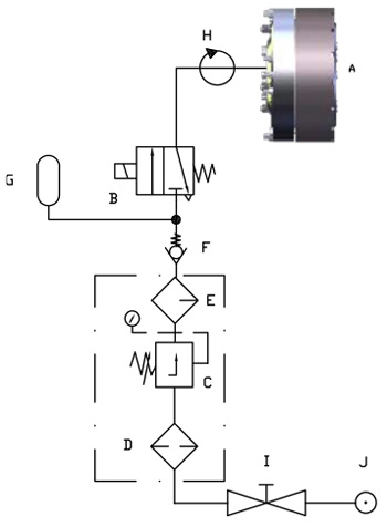
Schematic # 2: Displays a typical circuit diagram for a pneumatically actuated, dry clutch. The accumulator (G), enables fast actuation, and should be installed as close as possible to the clutch. The accumulator’s capacity is determined by the volume of the piping, fittings and the cylinderpiston volume of the clutch used in the application.
A. Clutch
B. 3/2 Control Valve
C. Pressure Limiting Valve
D. Filter
E. Lubricator
F. Non-Return Valve
G. Accumulator
H. Rotary Connection
I. Shut-off Valve
J. Main Supply
III. Hydraulic Actuation Wet operation with through shaft oil lubrication
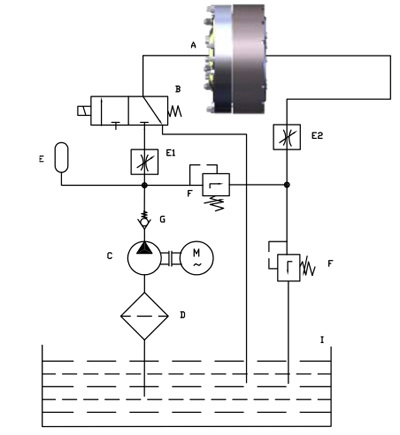
Schematic # 3: Displays a typical circuit diagram for a hydraulically actuated clutch with through shaft lubrication directed at the disc pack. During engagement, the excess oil flows through a cross drilled port through the shaft of the clutch. The throttle valve (E2) acts as the regulator of coolant flow.
A. Clutch
B. 3/2 Control Valve
C. Fixed Displacement Pump
D. Filter
E1. and E2. Throttle Valve
F. Pressure Limiting Valve
G. Non-Return Valve
H. Accumulator
I. Oil Reservoir