
 Search

Logan SAE PTO 600 Series –
Hydraulic & Pneumatic PTO ClutchSpecifications
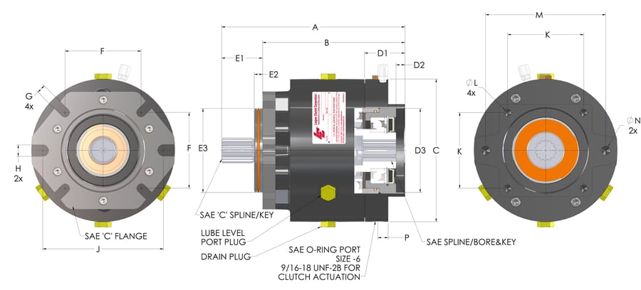
Mounting dimensions conforming to SAE J744
| Dimension | A | B | C | D1 | D2 | D3 | E1 | E2 | E3 | F | G | H | J | K | L | M | N | P |
|---|---|---|---|---|---|---|---|---|---|---|---|---|---|---|---|---|---|---|
| Dimensions in inches | 10.62 | 8.44 | 8.5 | 2.5 | 0.53 | 5.002 | 2.18 | 0.5 | 4.998 | 4.511 | 0.54 | 0.69 | 7.15 | 4.508 | 1/2-13UNC | 7.125 | 5/8-11UNC | 0.55 |
| Dimensions in millimeters | 269.8 | 214.4 | 215.9 | 63.5 | 13.5 | 127.1 | 55.4 | 12.7 | 126.9 | 114.6 | 13.7 | 17.5 | 114.5 | 1/2-13UNC | 181 | 5/8-11UNC | 14 |
* Standard configuration. Modified standards available.
SAE PTO 600 mounting dimensions (text version)
SAE PTO 600 dimensional data: all mounting dimensions conform to SAE J744 and are listed below for dimensions A through P in inches and millimeters. These are standard configuration dimensions; modified standards are available.
- Dimension A: 10.62 in (269.8 mm).
- Dimension B: 8.44 in (214.4 mm).
- Dimension C: 8.5 in (215.9 mm).
- Dimension D1: 2.5 in (63.5 mm).
- Dimension D2: 0.53 in (13.5 mm).
- Dimension D3: 5.002 in (127.1 mm).
- Dimension E1: 2.18 in (55.4 mm).
- Dimension E2: 0.5 in (12.7 mm).
- Dimension E3: 4.998 in (126.9 mm).
- Dimension F: 4.511 in (114.6 mm).
- Dimension G: 0.54 in (13.7 mm).
- Dimension H: 0.69 in (17.5 mm).
- Dimension J: 7.15 in.
- Dimension K: 4.508 in (114.5 mm).
- Dimension L: 1/2-13UNC thread.
- Dimension M: 7.125 in (181 mm).
- Dimension N: 5/8-11UNC thread.
- Dimension P: 0.55 in (14 mm).
PTO 600 Actual Static Torque****
| Units | 6100 Series | 6200 Series | 6300 Series | |
|---|---|---|---|---|
| Standard Units | Lbs.-Ft. | 912 | 985 | 985 |
| PSI (MAX.) | 120 | 200 | 320 | |
| Metric Units | Bar (MAX.) | 8.3 | 13.8 | 22.1 |
| Nm | 1237 | 1336 | 1336 | |
**** Torque ratings based on using ATF fluid as a lubricant. Refer to Logan IOM Manual for approved lubricants.
PTO 600 actual static torque by series (text version)
PTO 600 actual static torque and maximum pressure for the 6100, 6200 and 6300 Series, listed in standard and metric units. Torque ratings are based on using ATF fluid as a lubricant; refer to the Logan IOM Manual for approved lubricants.
- 6100 Series: actual static torque 912 lb-ft (1237 Nm); maximum pressure 120 PSI (8.3 bar).
- 6200 Series: actual static torque 985 lb-ft (1336 Nm); maximum pressure 200 PSI (13.8 bar).
- 6300 Series: actual static torque 985 lb-ft (1336 Nm); maximum pressure 320 PSI (22.1 bar).
| PTO 600 Series Input Shaft Option*** |
|---|
| SAE ‘C’ Spline 14T 12/24 DP |
| SAE ‘C-C’ Spline 17T 12/24 DP |
| SAE ‘C’ Ø 1.250 x 5/16 Sq. Key |
| SAE ‘C-C’ Ø 1.500 x 3/8 Sq. Key |
*** Contact Logan Clutch for alternative pump shaft options. The output end of the clutch (female spline/bore) is not capable of supporting any side load. Use overhung load adapters.
PTO 600 Series input shaft options (text version)
The PTO 600 Series is available with four input shaft options: two splined and two keyed, in SAE C and SAE C-C sizes. Contact Logan Clutch for alternative pump shaft options. The output end of the clutch (female spline/bore) is not capable of supporting any side load. Use overhung load adapters.
- SAE ‘C’ Spline 14T 12/24 DP: SAE C spline shaft, 14 teeth, 12/24 diametral pitch.
- SAE ‘C-C’ Spline 17T 12/24 DP: SAE C-C spline shaft, 17 teeth, 12/24 diametral pitch.
- SAE ‘C’ Ø 1.250 x 5/16 Sq. Key: SAE C keyed shaft, 1.250 in (31.75 mm) diameter with a 5/16 in (7.94 mm) square key.
- SAE ‘C-C’ Ø 1.500 x 3/8 Sq. Key: SAE C-C keyed shaft, 1.500 in (38.10 mm) diameter with a 3/8 in (9.53 mm) square key.
| PTO 600 Series Output (Pump) Shaft Option*** |
|---|
| SAE ‘C’ Spline 14T 12/24 DP |
| SAE ‘C-C’ Spline 17T 12/24 DP |
| SAE ‘C’ Ø 1.250 x 5/16 Sq. Key |
| SAE ‘C-C’ Ø 1.500 x 3/8 Sq. Key |
| Spline 21T 16/32 DP |
| Spline 23T 16/32 DP |
| SAE ‘D’ 13T 8/16 DP |
*** Contact Logan Clutch for alternative pump shaft options. The output end of the clutch (female spline/bore) is not capable of supporting any side load. Use overhung load adapters.
PTO 600 Series output (pump) shaft options (text version)
The PTO 600 Series is available with seven output (pump) shaft options: five splined and two keyed, including SAE C, SAE C-C and SAE D sizes. Contact Logan Clutch for alternative pump shaft options. The output end of the clutch (female spline/bore) is not capable of supporting any side load. Use overhung load adapters.
- SAE ‘C’ Spline 14T 12/24 DP: SAE C spline shaft, 14 teeth, 12/24 diametral pitch.
- SAE ‘C-C’ Spline 17T 12/24 DP: SAE C-C spline shaft, 17 teeth, 12/24 diametral pitch.
- SAE ‘C’ Ø 1.250 x 5/16 Sq. Key: SAE C keyed shaft, 1.250 in (31.75 mm) diameter with a 5/16 in (7.94 mm) square key.
- SAE ‘C-C’ Ø 1.500 x 3/8 Sq. Key: SAE C-C keyed shaft, 1.500 in (38.10 mm) diameter with a 3/8 in (9.53 mm) square key.
- Spline 21T 16/32 DP: spline shaft, 21 teeth, 16/32 diametral pitch.
- Spline 23T 16/32 DP: spline shaft, 23 teeth, 16/32 diametral pitch.
- SAE ‘D’ 13T 8/16 DP: SAE D spline shaft, 13 teeth, 8/16 diametral pitch.
PTO 600 Specifications
| Specification | U.S. | S.I. | |
|---|---|---|---|
| * Rated Static Torque (Maximum) | 600 ft.lbs. | 813 Nm | |
| Maximum HP/kW | 342 HP | 255 kW | |
| *Maximum RPM Under Load | 3000 RPM | 3000 RPM | |
| *Recommended Engagement Speed | Idle | Idle | |
| Rotation | Bi-rotation | Bi-rotation | |
| ** Maximum Actuation Pressure | 120, 200 or 320 PSI | 8.3, 13.8 or 22.1bar | |
| Min/Max Case Pressure at Input w/Optional High Pressure Seals | 7/50 PSI | 0.5/3.4 bar | |
| Min. Flow Rate Required (Actuation) | 1.5 GPM | 5.7 liters/min. | |
| Operating Media at Clutch (Oil or Air) | Standard | Standard | |
| Max. Back Pressure to Tank (Actuation) | 7 PSI | 0.5 bar | |
| Maximum Actuation Fluid Temperature | 180° F | 82° C | |
| Displacement: | 6100 Series (New/Worn) | 3.3/5.1 in3 | 54/83.5 cm3 |
| 6200 Series (New/Worn) | 2.4/3.6 in3 | 39.3/59 cm3 | |
| 6300 Series (New/Worn) | 1.5/2.3 in3 | 24.5/37.7 cm3 | |
| Weight (Approx.) | 52 lbs. | 24 kg | |
* Standard configuration. Modified standards available.
** Logan SAE PTO 600 Series clutches are available in three (3) different actuation pressures. Refer to part number to determine model configuration.
PTO 600 specifications (text version)
The PTO 600 weighs approximately 52 lbs. (24 kg), is bi-rotational, and is rated to a maximum static torque of 600 ft.lbs. (813 Nm). Rated static torque, maximum RPM under load and recommended engagement speed are for the standard configuration; modified standards are available. Logan SAE PTO 600 Series clutches are available in three (3) different actuation pressures. Refer to part number to determine model configuration. Each line below gives the U.S. value with the S.I. value in parentheses.
- Rated Static Torque (Maximum): 600 ft.lbs. (813 Nm).
- Maximum HP/kW: 342 HP (255 kW).
- Maximum RPM Under Load: 3000 RPM.
- Recommended Engagement Speed: Idle.
- Rotation: Bi-rotation.
- Maximum Actuation Pressure: 120, 200 or 320 PSI (8.3, 13.8 or 22.1 bar).
- Min/Max Case Pressure at Input w/Optional High Pressure Seals: 7/50 PSI (0.5/3.4 bar).
- Min. Flow Rate Required (Actuation): 1.5 GPM (5.7 liters/min.).
- Operating Media at Clutch (Oil or Air): Standard.
- Max. Back Pressure to Tank (Actuation): 7 PSI (0.5 bar).
- Maximum Actuation Fluid Temperature: 180° F (82° C).
- Displacement, 6100 Series: 3.3 in3 (54 cm3) new, 5.1 in3 (83.5 cm3) worn.
- Displacement, 6200 Series: 2.4 in3 (39.3 cm3) new, 3.6 in3 (59 cm3) worn.
- Displacement, 6300 Series: 1.5 in3 (24.5 cm3) new, 2.3 in3 (37.7 cm3) worn.
- Weight (Approx.): 52 lbs. (24 kg).
Disclaimer:
All Data and Dimensions are for reference only. Please contact Logan Clutch for detailed information.
Logan PTO Clutch Selection Procedure
Simplified Selection Procedure for Pump on Pad Configurations:
Determine pump face and shaft requirements. If mounting pad is identical, determine method of actuation, and select clutch from page 13 and 14 specifications.
Clutch Selection Procedures for Applications with Drive Shaft Input or Output, and Pumps not Conforming to SAE J744 (i.e. Fire Fighting Pumps)
Calculate the driven torque requirements for the application using one of the formula.
Torque (Lb./FT.) = (HP x 5250) / RPM
OR
Tc (Nm.) = (kW x 9550)/ RPM
Decide which series best fits your drive.
Using the appropriate series torque pressure to determine the model size.
Determine if the Series and models will:
1) Accommodate the shaft key, or spline
2) Operate at the required speed
3) Fit within the available space
Determine the Support/Mounting
Please complete the Application Fact Sheet details; scan and e-mail to: sales@loganclutch.com
HP = Horsepower
RPM = Clutch or Brake shaft speed
WR2 = Total inertia to be stopped (Ib.ft.2)
T = Required Torque (Lb./ Ft., Nm, Lb./in)
Tc = Clutch Torque (Lb./ Ft., Nm, Lb./in)
Tb = Brake Torque (Lb./ Ft., Nm, Lb./in)
t = Time to stop (seconds)
Torque & Horsepower Formulas
HP = (T(Lb./Ft.) x RPM) / 5250
Torque (Lb./Ft.) = (HP x 5250) / RPM
HP = (T(Lb./In.) x RPM) / 63025
Torque (Lb./In.) = (HP x 63025) / RPM
kW = (T(Nm.) x RPM) / 9550
Torque (Nm.) = (kW x 9550) / RPM
| Torque Conversion Calculators | Multiplier |
| Newton meters (Nm.) to Pound inches (lb.in.) | 8.851 |
| Pound inches (lb. in.) to Newton meters (Nm.) | 0.113 |
| Newton meters (Nm.) to Pounds feet (lb. ft.) | 0.738 |
| Pounds feet (lb.ft.) to Newton meters (Nm) | 1.356 |
| Horsepower Conversion Calculators | Multiplier |
| Horsepower (HP) to kW (Kilowatt) | 0.7457 |
| Kilowatt (kW) to Horsepower (HP) | 1.341 |
| Pressure Conversion Calculators | Multiplier |
| Bar to pounds per square inch (psi) | 14.5 |
| Pounds per square inch (psi) to Bar | 0.068 |
| Measurement Conversion Table | Multiplier |
| Millimeters (mm) to Inches (in) | 0.03937 |
| Inches (in) to Millimeters (mm) | 25.4 |
| Weight Conversion Table | Multiplier |
| Pounds (Lbs.) to Kilograms (Kg.) | 0.0453 |
| Kilograms (Kg.) to Pounds (Lbs.) | 2.205 |
| Volume Conversion Table | Multiplier |
| Gallons (Gal.) to Liters (Ltr.) | 3.785 |
| Liters (Ltr.) to Gallons (Gal.) | 0.2642 |
| Style | |
|---|---|
| S | SAE PTO |
PTO style options (text version)
This table lists the available PTO style codes; one style is shown.
- Style S: style code S designates an SAE PTO.
| Input Flange Size |
|---|
| B |
| C |
| D |
| E |
| F |
PTO input flange size options (text version)
This table lists the available PTO input flange sizes; five sizes are shown.
- Input flange size: available input flange sizes are B, C, D, E and F.
| Output Flange Size |
|---|
| A |
| B |
| C |
| D |
| E |
| F |
PTO output flange size options (text version)
This table lists the available PTO output flange sizes; six sizes are shown.
- Output flange size: available output flange sizes are A, B, C, D, E and F.
| Identifier | Rated Torque (ft.lbs.) | Rated Torque (Nm) |
|---|---|---|
| 2 | 200 | 271 |
| 3 | 300 | 407 |
| 4 | 400 | 542 |
| 6 | 600 | 814 |
| 10 | 1000 | 1356 |
| 12 | 1200 | 1627 |
| 15 | 1500 | 2034 |
| 22 | 2200 | 3000 |
Rated torque by serial number identifier (text version)
The identifier in a serial number indicates the unit’s rated torque. Eight identifiers are listed, from 2 (200 lb-ft) to 22 (2200 lb-ft).
- Identifier 2: a 2 in the serial number indicates a rated torque of 200 lb-ft (271 Nm).
- Identifier 3: a 3 in the serial number indicates a rated torque of 300 lb-ft (407 Nm).
- Identifier 4: a 4 in the serial number indicates a rated torque of 400 lb-ft (542 Nm).
- Identifier 6: a 6 in the serial number indicates a rated torque of 600 lb-ft (814 Nm).
- Identifier 10: a 10 in the serial number indicates a rated torque of 1000 lb-ft (1356 Nm).
- Identifier 12: a 12 in the serial number indicates a rated torque of 1200 lb-ft (1627 Nm).
- Identifier 15: a 15 in the serial number indicates a rated torque of 1500 lb-ft (2034 Nm).
- Identifier 22: a 22 in the serial number indicates a rated torque of 2200 lb-ft (3000 Nm).
| Identifier | Actuation Pressure (psi) | Actuation Pressure (bar) |
|---|---|---|
| 1 | 120 | 8.3 |
| 2 | 200 | 13.8 |
| 3 | 320 | 22.1 |
Actuation pressure by serial number identifier (text version)
The identifier in a serial number indicates the unit’s actuation pressure. Three identifiers are listed, from 1 (120 psi) to 3 (320 psi).
- Identifier 1: a 1 in the serial number indicates an actuation pressure of 120 psi (8.3 bar).
- Identifier 2: a 2 in the serial number indicates an actuation pressure of 200 psi (13.8 bar).
- Identifier 3: a 3 in the serial number indicates an actuation pressure of 320 psi (22.1 bar).
| Clutch Size • Standard – Input Size Male | ||||||||
|---|---|---|---|---|---|---|---|---|
| 200 | 300 | 400 | 600 | 1000 | 1200 | 1500 | 2200 | |
| 00 | Dry ‘B’ Spline | Dry ‘C’ Spline | Dry ‘C’ Spline | Dry ‘D’ Spline | Dry ‘F’ Spline | Dry ‘F’ Spline | Dry ‘F’ Spline | |
| 01 | Wet ‘B’ Spline | Wet ‘B’ Spline | Wet ‘C’ Spline | Wet ‘C’ Spline | Wet ‘D’ Spline | Wet ‘F’ Spline | Wet ‘F’ Spline | Wet ‘F’ Spline |
| 02 | Dry ‘B-B’ Spline | Dry ‘C-C’ Spline | Dry ‘C-C’ Spline | Dry ‘D’ Shaft | Dry ‘E’ Shaft | |||
| 03 | Wet ‘B-B’ Spline | Wet ‘B-B’ Spline | Wet ‘C-C’ Spline | Wet ‘C-C’ Spline | Wet ‘D’ Shaft | Wet ‘E’ Shaft | ||
| 04 | Dry ‘B’ Shaft | Dry ‘C’ Shaft | Dry ‘D&E’ Spline | Dry 2 7/16 w/ 5/8 | Dry 2 7/16 | |||
| 05 | Wet ‘B’ Shaft | Wet ‘C’ Shaft | Wet ‘D&E’ Spline | |||||
| 06 | Dry ‘B-B’ Shaft | Dry ‘C-C’ Shaft | ||||||
| 07 | Wet ‘B-B’ Shaft | Wet ‘C-C’ Shaft | ||||||
| 08 | Dry ‘C’ Spline | |||||||
| 09 | Wet ‘C’ Spline | |||||||
Standard clutch input options (male input size) by clutch size (text version)
Male input options for standard clutches are listed for eight clutch sizes, 200 through 2200, with each option on a numbered row from 00 to 09.
- Clutch size 200: 01: wet ‘B’ spline; 03: wet ‘B-B’ spline.
- Clutch size 300: 00: dry ‘B’ spline; 01: wet ‘B’ spline; 02: dry ‘B-B’ spline; 03: wet ‘B-B’ spline; 04: dry ‘B’ shaft; 05: wet ‘B’ shaft; 06: dry ‘B-B’ shaft; 07: wet ‘B-B’ shaft; 08: dry ‘C’ spline; 09: wet ‘C’ spline.
- Clutch size 400: 00: dry ‘C’ spline; 01: wet ‘C’ spline; 02: dry ‘C-C’ spline; 03: wet ‘C-C’ spline.
- Clutch size 600: 00: dry ‘C’ spline; 01: wet ‘C’ spline; 02: dry ‘C-C’ spline; 03: wet ‘C-C’ spline; 04: dry ‘C’ shaft; 05: wet ‘C’ shaft; 06: dry ‘C-C’ shaft; 07: wet ‘C-C’ shaft.
- Clutch size 1000: 00: dry ‘D’ spline; 01: wet ‘D’ spline; 02: dry ‘D’ shaft; 03: wet ‘D’ shaft.
- Clutch size 1200: 00: dry ‘F’ spline; 01: wet ‘F’ spline; 02: dry ‘E’ shaft; 03: wet ‘E’ shaft; 04: dry ‘D&E’ spline; 05: wet ‘D&E’ spline.
- Clutch size 1500: 00: dry ‘F’ spline; 01: wet ‘F’ spline; 04: dry 2 7/16 w/ 5/8.
- Clutch size 2200: 00: dry ‘F’ spline; 01: wet ‘F’ spline; 04: dry 2 7/16.
| Dual Actuation - 120 and 320 PSI |
|---|
| Designation applies to rated torque models 1000, 1200 and 1500 series |
Dual actuation designation (text version)
The dual actuation designation covers two actuation pressures and is limited to specific rated torque models.
- Dual actuation: actuation pressures of 120 psi (8.3 bar) and 320 psi (22.1 bar); this designation applies to rated torque models in the 1000, 1200 and 1500 series.
| Clutch Size • Standard – Output Size Female | ||||||||
|---|---|---|---|---|---|---|---|---|
| Identifier | 200 | 300 | 400 | 600 | 1000 | 1200 | 1500 | 2200 |
| 01 | ‘B’ Spline | ‘B’ Spline | ‘C’ Spline | ‘C’ Spline | ‘D’ & ‘E’ Spline | ‘F’ Spline | ‘F’ Spline | ‘F’ Spline |
| 02 | ‘B-B’ Spline | ‘B-B’ Spline | ‘C-C’ Spline | ‘C-C’ Spline | ‘D’ & ‘E’ Bore/Key | ‘D’ & ‘E’ Spline | ‘D’ & ‘E’ Spline | ‘D’ Spline |
| 03 | ‘B-B’ Bore/Key | ‘B’ Bore/Key | ‘C’ Bore/Key | ‘C’ Bore/Key | Spline 27T 16/32 DP | Spline 33T 16/32 DP | ‘D’ & ‘E’ Bore/Key | ‘D’ Bore 1.75 w/ 7/16 Key |
| 04 | ‘B’ Bore/Key | ‘B-B’ Bore/Key | Spline 21T 16/32 DP | ‘C-C’ Bore/Key | Spline 33T 16/32 DP | Spline 23T 16/32 DP | Bore 2-7/16 w/ 5/8 Key | Bore 2-7/16 w/ 5/8 Key |
| 05 | ‘C’ Spline | ‘D’ & ‘E’ Spline | Spline 16T 10/20 DP | Spline 27T 16/32 DP | Spline 27T 16/32 DP | Spline 27T 16/32 DP | ||
| 06 | Spline 21T 16/32 DP | Spline 16T 8/16 DP | Spline 33T 16/32 DP | Spline 33T 16/32 DP | ||||
| 07 | Spline 23T 16/32 DP | DIN 5480 | ||||||
| 08 | ‘B’ Spline | 50 mm bore 14 mm key | ||||||
| 09 | Spline 27T 16/32 DP | ‘F’ Spline | ||||||
| 10 | ‘B-B’ Spline | |||||||
Standard clutch output options (female output size) by clutch size and serial number identifier (text version)
The two-digit identifier (01 to 10) in a standard clutch’s serial number indicates its female output option. What each identifier means depends on the clutch size, from 200 through 2200.
- Clutch size 200: identifier 01 indicates ‘B’ spline; identifier 02 indicates ‘B-B’ spline; identifier 03 indicates ‘B-B’ bore/key; identifier 04 indicates ‘B’ bore/key.
- Clutch size 300: identifier 01 indicates ‘B’ spline; identifier 02 indicates ‘B-B’ spline; identifier 03 indicates ‘B’ bore/key; identifier 04 indicates ‘B-B’ bore/key; identifier 05 indicates ‘C’ spline.
- Clutch size 400: identifier 01 indicates ‘C’ spline; identifier 02 indicates ‘C-C’ spline; identifier 03 indicates ‘C’ bore/key; identifier 04 indicates spline 21T 16/32 DP.
- Clutch size 600: identifier 01 indicates ‘C’ spline; identifier 02 indicates ‘C-C’ spline; identifier 03 indicates ‘C’ bore/key; identifier 04 indicates ‘C-C’ bore/key; identifier 05 indicates ‘D’ & ‘E’ spline; identifier 06 indicates spline 21T 16/32 DP; identifier 07 indicates spline 23T 16/32 DP; identifier 08 indicates ‘B’ spline; identifier 09 indicates spline 27T 16/32 DP; identifier 10 indicates ‘B-B’ spline.
- Clutch size 1000: identifier 01 indicates ‘D’ & ‘E’ spline; identifier 02 indicates ‘D’ & ‘E’ bore/key; identifier 03 indicates spline 27T 16/32 DP; identifier 04 indicates spline 33T 16/32 DP; identifier 05 indicates spline 16T 10/20 DP; identifier 06 indicates spline 16T 8/16 DP; identifier 07 indicates DIN 5480; identifier 08 indicates 50 mm bore 14 mm key; identifier 09 indicates ‘F’ spline.
- Clutch size 1200: identifier 01 indicates ‘F’ spline; identifier 02 indicates ‘D’ & ‘E’ spline; identifier 03 indicates spline 33T 16/32 DP; identifier 04 indicates spline 23T 16/32 DP; identifier 05 indicates spline 27T 16/32 DP.
- Clutch size 1500: identifier 01 indicates ‘F’ spline; identifier 02 indicates ‘D’ & ‘E’ spline; identifier 03 indicates ‘D’ & ‘E’ bore/key; identifier 04 indicates bore 2-7/16 w/ 5/8 key; identifier 05 indicates spline 27T 16/32 DP; identifier 06 indicates spline 33T 16/32 DP.
- Clutch size 2200: identifier 01 indicates ‘F’ spline; identifier 02 indicates ‘D’ spline; identifier 03 indicates ‘D’ bore 1.75 w/ 7/16 key; identifier 04 indicates bore 2-7/16 w/ 5/8 key; identifier 05 indicates spline 27T 16/32 DP; identifier 06 indicates spline 33T 16/32 DP.
How to match your pump with a Logan SAE PTO Clutch
Using the diagrams and table below, determine what hydraulic pump you have or require.
Count the number of mounting holes and measure the distance between the holes.
Count the No. of teeth (if there is a spline) or (if there is a key), measure the key width.
Measure the diameter of the spline or straight shaft.
Measure the length of the shaft from the mounting face to the end of the shaft.
Measure the length of the full spline or key end of shaft towards the pump.
Measure the pilot diameter of the pump.
Utilize the chart and diagrams below to determine what pump you have or require.
Match the Male / Input of the pump with a Logan SAE PTO Clutch.
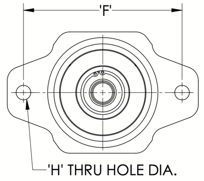
Mounting Flange 2-Bolt
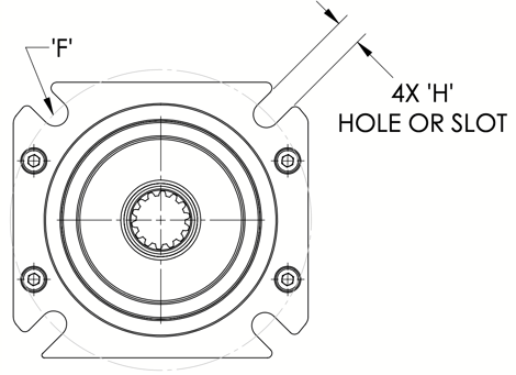
Mounting Fland 4-Bolt
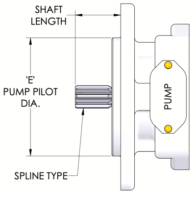
Splined Shaft
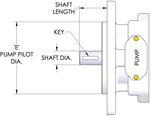
Keyed Shaft
| Pump Mount Flange & Shaft Size SAE J744 | 2-Bolt Pump | 4-Bolt Pump | Shaft Dimensions | |||||||
|---|---|---|---|---|---|---|---|---|---|---|
| ‘E’ Pilot Dia | ‘F’ B.C. | ‘H’ Hole Diam. | ‘E’ Pilot Dia | ‘F’ B.C. | ‘H’ Hole Diam. | Spline Spec. | Spline Shaft | Shaft & Key Diam. | Shaft & Key Shaft Length | |
| A-A | 2.000 | 3.250 | 0.406 | None | 9T 20/40 | 1.06 | 0.500 x .125 | 1.06 | ||
| A | 3.250 | 4.187 | 0.438 | 9T 16/32 | 1.25 | 0.625 x .156 | 1.25 | |||
| B | 4.000 | 5.750 | 0.562 | 4.000 | 5.000 | 0.562 | 13T 16/32 | 1.62 | 0.875 x .250 | 1.62 |
| B-B | 15T 16/32 | 1.81 | 1.000 x .250 | 1.81 | ||||||
| C | 5.000 | 7.125 | 0.688 | 5.000 | 6.375 | 0.562 | 14T 12/24 | 2.19 | 1.250 x .312 | 2.19 |
| C-C | 17T 12/24 | 2.44 | 1.500 x .375 | 2.44 | ||||||
| D | 6.000 | 9.000 | 0.812 | 6.000 | 9.000 | 0.812 | 13T 8/16 | 2.94 | 1.750 x .437 | 2.94 |
| E | 6.500 | 12.500 | 1.062 | 6.500 | 12.500 | 0.812 | 13T 8/16 | 2.94 | 1.750 x .437 | 2.94 |
| F | 7.000 | 13.781 | 1.062 | 7.000 | 13.781 | 1.062 | 15T 8/16 | 3.44 | None | None |
SAE J744 pump mount flange and shaft dimensions by size (text version)
Pump mount flange and shaft dimensions are listed for nine SAE J744 sizes, A-A through F, covering 2-bolt pumps, 4-bolt pumps and shaft dimensions.
- Size A-A: 2-bolt pump ‘E’ pilot dia 2.000, ‘F’ B.C. 3.250, ‘H’ hole diam. 0.406; 4-bolt pump: none; spline spec. 9T 20/40, spline shaft 1.06, shaft & key diam. 0.500 x .125, shaft & key shaft length 1.06.
- Size A: 2-bolt pump ‘E’ pilot dia 3.250, ‘F’ B.C. 4.187, ‘H’ hole diam. 0.438; 4-bolt pump: none; spline spec. 9T 16/32, spline shaft 1.25, shaft & key diam. 0.625 x .156, shaft & key shaft length 1.25.
- Size B: 2-bolt pump ‘E’ pilot dia 4.000, ‘F’ B.C. 5.750, ‘H’ hole diam. 0.562; 4-bolt pump ‘E’ pilot dia 4.000, ‘F’ B.C. 5.000, ‘H’ hole diam. 0.562; spline spec. 13T 16/32, spline shaft 1.62, shaft & key diam. 0.875 x .250, shaft & key shaft length 1.62.
- Size B-B: 2-bolt pump ‘E’ pilot dia 4.000, ‘F’ B.C. 5.750, ‘H’ hole diam. 0.562; 4-bolt pump ‘E’ pilot dia 4.000, ‘F’ B.C. 5.000, ‘H’ hole diam. 0.562; spline spec. 15T 16/32, spline shaft 1.81, shaft & key diam. 1.000 x .250, shaft & key shaft length 1.81.
- Size C: 2-bolt pump ‘E’ pilot dia 5.000, ‘F’ B.C. 7.125, ‘H’ hole diam. 0.688; 4-bolt pump ‘E’ pilot dia 5.000, ‘F’ B.C. 6.375, ‘H’ hole diam. 0.562; spline spec. 14T 12/24, spline shaft 2.19, shaft & key diam. 1.250 x .312, shaft & key shaft length 2.19.
- Size C-C: 2-bolt pump ‘E’ pilot dia 5.000, ‘F’ B.C. 7.125, ‘H’ hole diam. 0.688; 4-bolt pump ‘E’ pilot dia 5.000, ‘F’ B.C. 6.375, ‘H’ hole diam. 0.562; spline spec. 17T 12/24, spline shaft 2.44, shaft & key diam. 1.500 x .375, shaft & key shaft length 2.44.
- Size D: 2-bolt pump ‘E’ pilot dia 6.000, ‘F’ B.C. 9.000, ‘H’ hole diam. 0.812; 4-bolt pump ‘E’ pilot dia 6.000, ‘F’ B.C. 9.000, ‘H’ hole diam. 0.812; spline spec. 13T 8/16, spline shaft 2.94, shaft & key diam. 1.750 x .437, shaft & key shaft length 2.94.
- Size E: 2-bolt pump ‘E’ pilot dia 6.500, ‘F’ B.C. 12.500, ‘H’ hole diam. 1.062; 4-bolt pump ‘E’ pilot dia 6.500, ‘F’ B.C. 12.500, ‘H’ hole diam. 0.812; spline spec. 13T 8/16, spline shaft 2.94, shaft & key diam. 1.750 x .437, shaft & key shaft length 2.94.
- Size F: 2-bolt pump ‘E’ pilot dia 7.000, ‘F’ B.C. 13.781, ‘H’ hole diam. 1.062; 4-bolt pump ‘E’ pilot dia 7.000, ‘F’ B.C. 13.781, ‘H’ hole diam. 1.062; spline spec. 15T 8/16, spline shaft 3.44, shaft & key diam.: none, shaft & key shaft length: none.